Semi-conductor Rotor Starters of TE - 25 Range for Slip-ring Induction Motors
Introduction:
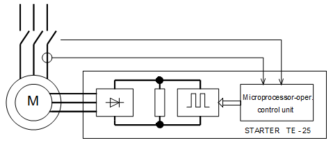
The semi-conductor rotor starters are determined for slip-ring induction motors with output ranging from 50 kW to 2.5 MW. In contrast to classic resistance oil-cooled rotor starters with contactor-rejected out of operation resistance stages, they make use of state-of-the-art power semi-conductor elements by Siemens, microprocessor control and solid welded cast-iron air-cooled resistor.
This progressive starter concept provides the following advantages:
-
Fluent start of the induction motor
-
Observance of high starting torques
-
Optimum microprocessor-controlled motor starting characteristics
-
High numer of starts per hour due to the use of air-cooled resistors
-
Possibility of using the starter for motor-speed regulation
-
Low maintenance cost as compared with liquid and oil-cooled starters
-
Longer service life and higher reliability of starters
-
Easy replacement of old starters, simple connection.
-
RS 485 serial communication interface by Modbus RTU protocol for connect. to central control
Starter Flow Chart:

TE - 25 Starters Type Range and Parameters:
The starter as a compact unit is located in a steel-sheet switchgear of cubicle-type containing all the needed power, control and protection circuits. The starters are provided in following size categories:
| Starter Type | Motor Output (kW) | Max.rotor voltage (V) | Max. Rotor current (A) | Starting Density (sp./h) | Heat Capacity (kJ) |
|---|---|---|---|---|---|
| TE 25-0 | 30 - 50 | 300 | 150 | 10 | 10 000 |
| TE 25-1 | 63 - 200 | 400 | 200 | 10 | 20 000 |
| TE 25-2 | 90 - 400 | 600 | 300 | 8 | 40 000 |
| TE 25-3 | 180 - 800 | 800 | 450 | 5 | 60 000 |
| TE 25-4 | 400 - 1500 | 1500 | 800 | 3 | 120 000 |
| TE 25-5a | 1000 - 3000 | 1700 | 1200 | 3 | 240 000 |
| TE 25-5b | 1000 - 3000 | 4000 | 800 | 3 | 240 000 |
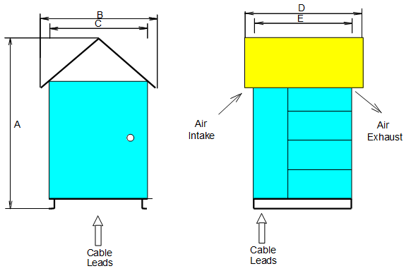
TE - 25 Starters Design and Dimensions:

Sizes and Weight:
| Typ | A (mm) | B (mm) | C (mm) | D (mm) | E (mm) | Hmotnost (kg) |
|---|---|---|---|---|---|---|
| TE 25-0 | 1650 | 1030 | 830 | 750 | 460 | 120 |
| TE 25-1 | 1650 | 1030 | 830 | 1000 | 860 | 230 |
| TE 25-2 | 1650 | 1030 | 830 | 1000 | 860 | 350 |
| TE 25 3 | 1650 | 1030 | 830 | 1000 | 860 | 600 |
| TE 25-4 | 1650 | 1030 | 830 | 1600 | 1460 | 900 |
| TE 25-5 | 2100 | 1200 | 800 | 2100 | 1200 | 1600 |
Installation and connection:
The starter cubicle may be installed near the electric motors and is intended for outdoor environment. Power cables from the motor are brought via bushings in the cubicle floor and are connected by M 12 screws and cable eyes to the starter´s connecting busbars. Auxiliary supply, measuring and control cables are connected to the terminal block of external attachments.
Other Technical Parameters:
-
Forced air cooling of the cubicle: 760 m3 / h
-
Enclosure of starter cubicle / resistors / electronics: IP 54 / IP 41 / IP 65
-
Auxiliary supply: 3 x 400V / 50 Hz, max. 1000 VA
Data for Orders:
Motor output, nominal rotor voltage and current, starting time, severity of start, number of consecutive starts, starting density (permissible number of starts per hour), working environment.

